Quadropod - Switching to interrupts and timers
After a bit of experimentation I finally figured that working with servos from the main program loop is not very efficient and precise. The main issue I’ve been facing is synchronous and controlled rotation of several servos to different angles.
Let’s have a look at the image below:
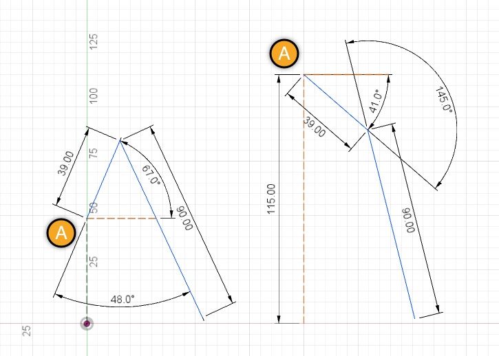
What you see is a schematical look of the limb (leg) position. Point “A” is where the limb is connected to the body, then the first segment (39mm in length) and the second segment (90mm). In the first schema the body stays at the height of 25mm above the ground.
Now we want to lift the point “A” to 115mm strictly vertically. Given that we involve all limbs of the bot into the same motion, we need to maintain the point of contact with the floor at the very same position. In order to do this, angles of all servos should update synchronously.
If we just give the new angle to all of them, as calculated and shown in the second schema, they will wreak havoc. The reason being is that the angular speed of a servo is constant. The MG90S I use has roughly 60 degrees per 100ms turn speed. Evidently it will take different time to servos to turn to different angles. Forget about synchronicity. Motion looks hectic and inefficient.
Ideally, each servo speed should be controlled, but that’s not how it works.
Synchronization
I came up with the idea of breaking the full range of motion from angle A to angle B into small pieces for each servo and making sure every one of them is in sync at these control points. Here’s an example.
Assume that we need to turn Servo A to 60 degrees and Servo B to 120 degrees. Let’s also assume that we have control interval of 20ms. Servo speed is 12 degrees per 20ms (60 deg * 20ms / 100ms). It means that we need 10 control intervals to turn Servo B to the target angle at full speed and only 5 intervals for Servo A. We pick the largest number as otherwise the Servo B won’t be able to catch up. Here’s what we have so far:
You need to be careful choosing the control point interval. It should be longer than it takes to your interrupt code to do the work. If it takes longer, you will be skipping control points and breaking the smoothness of motion.
Also note, that you will probably need to enable interrupts to work with Wire module for sending commands to the driver shield over I2C. If it’s the case, global interrupts must be enabled inside the interrupt vector and thus there’s a chance that your function is interrupted with another control point event bringing even more mess.
- Servo A angle to go = 60 deg
- Servo B angle to go = 120 deg
- Control interval = 20ms
- Number of intervals = 10
We can figure that during each interval Servo A should turn 6 deg (and wait 10ms until the next value is given), and Servo B - 12deg. It is easy to calculate the actual values to be sent to each servo for every control interval, but how do we execute the plan?
Interrupts and Timers
Here’s the point where I turned to hardware interrupts and timers of ATMega 328 that I’m using (Arduino UNO board).
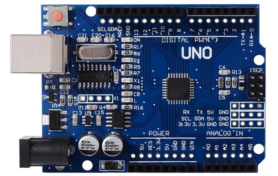
It has three timers that are equipped with prescalers and can trigger interrupts when the counters reach a certain value. It’s pretty easy to configure Timer 1 to get us 20ms interval interrupts.
With interrupts happening at regular periods, it’s a matter of giving the sequence of values a function needs to set to each servo involved in motion to have them update synchronously and in the controlled way.
The bonus is that you can do more calculations, read remote controller commands and anything else while the hardware executes your plan without blocking the main loop. Very nice!
Happy making!
P.S. If you need more info on how to do that, here’s a great intro with all the details you might possibly need: